Try and work out how this works! A remote controller through Arduino that works via Bluetooth and an Android smartphone (i.e. a apk). More details to follow.
In this week, we tried expanding the "blink" tutorial to cover FOUR lights! Extraordinary, I know.
Here's the Blink tutorial for Arduino for those unaware:
Hardware Required
Arduino Board
LED
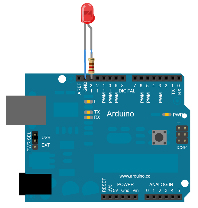
Circuit
To build the circuit, attach a 220-ohm resistor to pin 13. Then attach the long leg of an LED (the positive leg, called the anode) to the resistor. Attach the short leg (the negative leg, called the cathode) to ground. Then plug your Arduino board into your computer, start the Arduino program, and enter the code below.
Most Arduino boards already have an LED attached to pin 13 on the board itself. If you run this example with no hardware attached, you should see that LED blink.
Schematic
Code
In the program below, the first thing you do is to initialize pin 13 as an output pin with the line
pinMode(13, OUTPUT);
In the main loop, you turn the LED on with the line:
digitalWrite(13, HIGH);
This supplies 5 volts to pin 13. That creates a voltage difference across the pins of the LED, and lights it up. Then you turn it off with the line:
digitalWrite(13, LOW);
That takes pin 13 back to 0 volts, and turns the LED off. In between the on and the off, you want enough time for a person to see the change, so the delay() commands tell the Arduino to do nothing for 1000 milliseconds, or one second. When you use the delay() command, nothing else happens for that amount of time.
Video Tutorial
And the code!
/*
Blink
Turns on an LED on for one second, then off for one second, repeatedly.
This example code is in the public domain.
*/
// Pin 13 has an LED connected on most Arduino boards.
// give it a name:
int led = 13;
// the setup routine runs once when you press reset:
void setup() {
// initialize the digital pin as an output.
pinMode(led, OUTPUT);
}
// the loop routine runs over and over again forever:
void loop() {
digitalWrite(led, HIGH); // turn the LED on (HIGH is the voltage level)
delay(1000); // wait for a second
digitalWrite(led, LOW); // turn the LED off by making the voltage LOW
delay(1000); // wait for a second
}